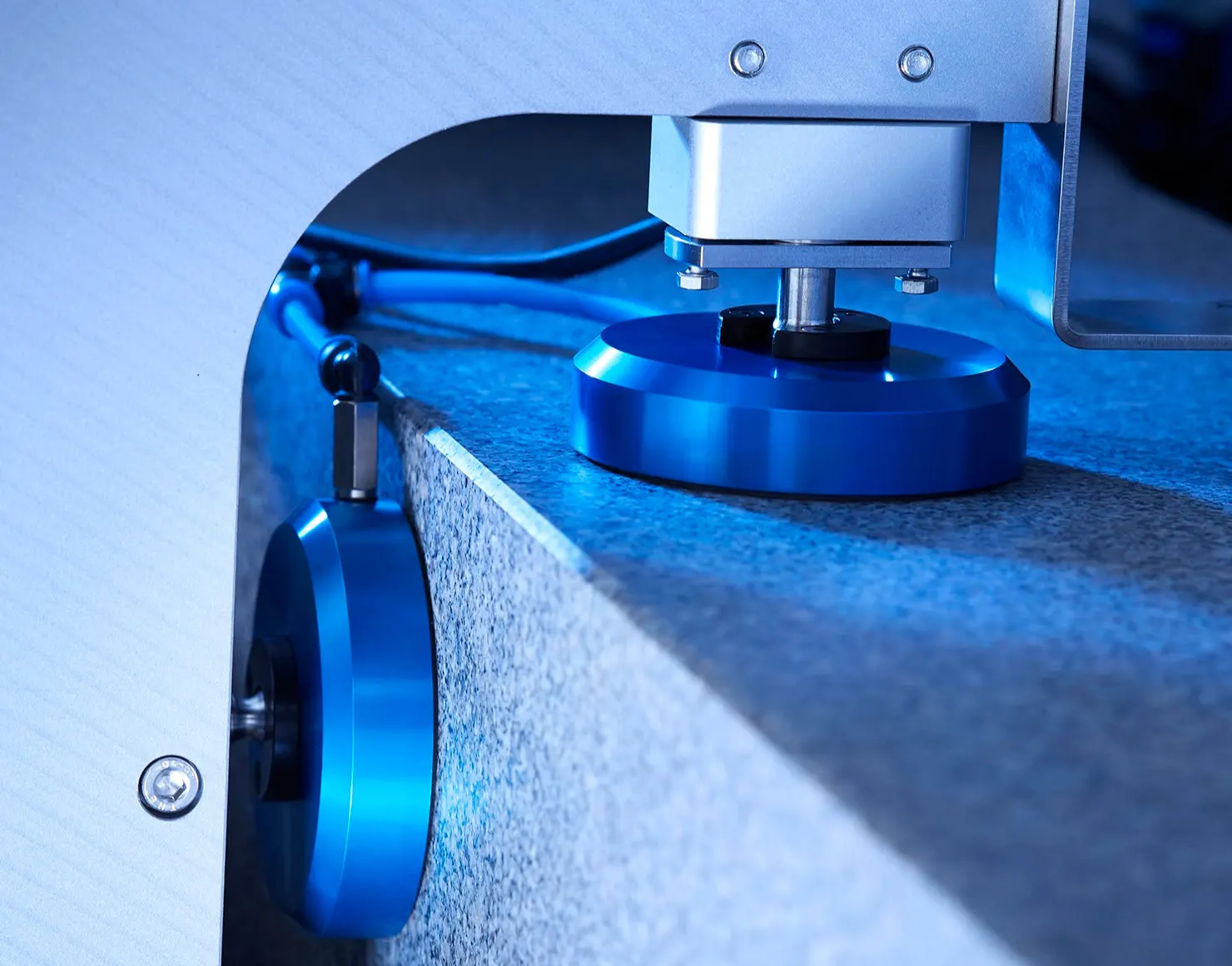
A small layer of compressed air is used to provide an air cushion between two surfaces, allowing them to slide over one another with no resistance. This sort of bearing technology is known as an air bearing, also known as an aerostatic bearing or an air-supported bearing. This technology is frequently employed in a variety of industrial and precision applications where movement must be incredibly exact and smooth.
How Air Bearings works:
1. When the air bearing is not activated, the mating surfaces come into direct physical contact.

2. Either through relative motion or external pressure, a thin layer of fluid (such as air or gas) becomes pressurized between the stationary objects.

3. Due to a preload force maintaining a narrow gap, the air gradually exits into the atmosphere, leading to a gradual pressure buildup.

4. Once the pressure reaches a significant level, the resultant force prompts a slight movement of the upper element away from the stationary one, eventually achieving a state of static balance.

5. The distance of this air gap is influenced by both the total applied load and the fluid pressure between them; greater pressure leads to a larger gap between the surfaces.
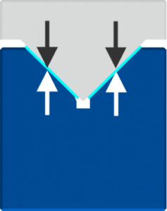
At this point, movement is frictionless and wear-free since there is no contact between the mating surfaces. In order to achieve maximum functioning, it is essential to provide the correct air gap during setup and operation. Our gap-sensing air bearings provide an effective and occasionally unique method to gauge the thickness of the air cushion.
Air bearings are superior to conventional bearings like the cross roller example stated above in their ability to offer astonishingly accurate motion. Air bearings distinguish themselves in a distinct category by exhibiting average straightness variations of < 0.1 microns per 100mm and rotational accuracy of less than 0.02 microns.
Source of accuracy
Air bearings avoid this problem by not physically contacting the riding surface, whereas the roller in the aforementioned mechanical bearing tracks the defects of the v-groove, causing noise and inducing variations in motion straightness. As a result, all of the flaws present on the surfaces in contact are reflected in the motion precision attained in air bearings. Inconsistencies in the larger area next to the bearing face cause variations in the height of movement.
Source of repeatability
The foundation for the extraordinary repeatability of air bearings is the absence of wear, which ensures that accuracy remains constant over the course of the bearing lifespan. Air bearings may frequently achieve motion repeatability of less than 0.02 microns, with the positioning system’s accuracy frequently acting as the main restriction. With the use of this feature, makers of machine tools with linear stages may create a positional error profile for a particular axis. The machine’s control algorithm incorporates the discovered straightness deviations, allowing for adjustment using one or more of the perpendicular axes. As it relaxes the necessary form tolerances for the guideways, this method helps to lower the costs related to manufacturing stages.
High speed operation
Designers frequently use ball or roller topologies for high-speed applications needing mechanical bearings because of their decreased friction. Due to heat production and wear on the contacting surfaces, these options have limits in high-speed operation. Moreover, increasing stage acceleration can cause ball/roller creeping, cage dragging, or roller sliding, all of which are made worse by added load. Thankfully, using air bearings eliminates these issues. Heat production often doesn’t start until speeds exceed 40–60 meters per second due to the low viscosity of gases like air (over 100 miles per hour). By changing the bearing surface design or widening the air gap, this influence can be reduced. With accelerations exceeding 14g, linear motor-powered stages have been successfully constructed. Interestingly, despite the air bearing’s shortcomings, all these benefits
As previously mentioned, either relative motion or an external pressure air source can induce the pressurization of the gap. This distinction categorizes air bearings into two broad groups:
- Aerodynamic (requiring relative motion to generate air film)
- Aerostatic (requiring an external pressure source to generate air film)
What is an aerodynamic air bearing?
Aerodynamic bearings, often referred to as self-acting bearings, can have unique characteristics built into the mating surfaces that operate as tiny pumps. These mating surfaces may be in close proximity while at rest. Air molecules from the atmosphere are dragged into the gap as they move in relation to one another, collecting and increasing pressure. A pressure gradient caused by velocity that builds across the gap as speed rises creates increased pressure between the surfaces, which supports the weight. The fact that load capacity depends on surface speed implies that the air bearing cannot support any weight when the speed is zero.
Aerodynamic bearings typically struggle with lowered load-carrying capacities. Moreover, because of the beginning and stopping friction caused by the zero-load phenomena at zero speed, the air bearing surfaces may somewhat deteriorate. Self-acting bearings offer a wide range of industrial applications despite significant drawbacks. The magnetic read/write heads of disk-based hard drive memory storage are a notable example. In this case, a thrust force between the disc surface and the head is supported by a flat air film. An armature gently presses the head on the surface, while a motor generates relative motion by rotating the disc. The head rises above the disc surface as pressure increases. The air bearing head’s flight distance has been reduced by hard drive advancements to as small as 3 nanometers, or nearly 30,000 times thinner. than an average sheet of notebook paper. Such minute air gaps pose fabrication challenges, addressed in the Manufacturing Challenges section below.
Yet, if the relative velocities of the surfaces are sufficiently high, large air gaps can be tolerated. The pressure increases together with the velocity. The space between the surfaces might widen due to the increasing pressure. Surprisingly, flat aerodynamic pads operating at hypersonic relative speeds have been designed to carry heavy weights weighing several thousand pounds. Concepts like the projected Hyperloop transportation system could benefit from the use of such bearings.
Again, the ability of aerodynamic air bearings to operate independently without an external pressure source is their main benefit. The area of the bearing and the relative velocities of the mating surfaces define the load capacity of the bearing. As a result, aerodynamic air bearings may be appropriate in the following circumstances:
- Where the application requires lack of an external pressure source
- Where the application can provide enough relative velocity to generate lift for a given size of the bearing
Aerostatic air bearing principles
Applications that allow an external pressure source to provide air to the bearing are immune to the negative effects of surface wear during motion initiation or cessation. Bearings functioning in this manner are termed as aerostatic. This variant can sustain its full design load at both zero and high speeds, devoid of stiction and wear. At rest, the mating surfaces of the bearing are in direct contact under an applied load. Typically, an air tube connected to the bearing housing delivers pressurized air or gas. Internal features within the bearing guide the air towards the gap interface, facilitated by various methods elaborated below. As previously explained, the limited clearance upheld by the applied load hinders swift air molecule escape between the mating surfaces and into the atmosphere. This leads to pressure accumulation, steadily building until the resultant force pushes the mating surfaces apart. The gap widens until equilibrium is achieved between the inlet pressure and the restriction of air flow. Consequently, the air bearing enters a state of frictionless movement.
Aerostatic air bearings have load capacity limitations that are completely based on the supply pressure and the durability of the mechanical parts. Surprisingly, air bearings can handle weights up to several tonnes when properly engineered without causing friction or wear on the mating surfaces.
The manner in which pressurized gas enters the gap further divides the aerostatic category into distinct types:
- Porous surface
- Partial porous surface
- Discrete Orifice feeding
- Slot feeding
- Groove feeding
Porous Surface
A porous material, such as carbon, bronze, or other materials, directs air towards the gap while regulating its passage. Superior pressure distribution provided by this bearing classification leads to a somewhat higher load capacity and rigidity. Particularly with porous carbon, accidental contact between the mating surfaces during relative motion doesn’t significantly affect the bearing’s functionality. Yet, when porous materials are manufactured, this type of bearing may operate with the discharge of tiny particles. This could not be a good thing, especially in cleanroom environments where semiconductor wafer production takes place.
Partial Porous Surface
An area of the air bearing’s surface has a permeable component that makes it easier for air to move through. By combining solid and porous surfaces, damping can be improved while dealing with dynamic situations. The input ring that is being provided provides even air distribution. It can be difficult to control the permeability of the porous material throughout its relatively small area, which frequently requires the presence of a valve or similar restrictor inside the housing to control the flow rate.
Discrete Orifice Feeding
The air bearing’s face has one or more tiny holes that prevent air from reaching the film. Little flying height fluctuations from bearing to bearing may be provided by this approach. Orifice-based flat air bearings are capable of tilts as small as 0.1 microns. Orifice air bearings can be made to emit less than five 0.1 micron particle emissions per minute, despite the fact that they are not as durable as the porous carbon kind. Orifice type bearings frequently have the lowest production costs due to their relative simplicity.
Slot feeding
Similar to orifice air bearings, but with a rectangular slot in place of the tiny hole. This method of air distribution is more consistent and calculable than orifice bearings, and it is frequently employed in cylindrical journal air bearings. At high journal shaft eccentricity points, slot supplied air bearings are more rigid. They often cost more to produce in small numbers.
Groove Feeding
Several tiny grooves are fabricated axially into the bearing surface leading from an air source volume in the Centre of the journal in cylindrical journal air bearings as well. Although this approach may produce a film with extremely high stiffness and symmetrical air flow distribution, it can be more expensive than orifice or slot feeding air bearings.
Performance Characteristics
The usual criteria for evaluation when choosing an air bearing are load capacity and rigidity. The effective bearing surface area and film pressure both have an impact on load capacity. Typically, the average film pressure is equal to around 40% of the input pressure. Hence, an air bearing that is flat and has an area of one square inch and operates at an intake pressure of 80 psig can support around 32 pounds (40% x 80 psig x 1 inch2). Another crucial characteristic is stiffness, which evaluates the bearing’s resistance to fluctuations in load-induced changes in the air gap. The rigidity of a flat air bearing is around 100,000 lbs/inch per square inch. This means that an air bearing with an area of 10 square inches has a rigidity of around 1,000,000 pounds per inch. Both these attributes, alongside others like flow rate, are meticulously measured and documented for each of our manufactured air bearings.
What about hydrodynamic and hydrostatic bearings?
These bearings function similarly to air bearings in that a liquid is used as the pressurised medium. Due to the increased viscosity of the liquid, liquid film bearings perform better than gas film bearings when comparing sizes in terms of load capacity and stiffness. However increasing viscosity also causes more friction and heat to be produced. These bearings need systems to collect and recirculate the liquid as it departs the film gap, unlike air bearings that can simply vent to the environment. This recirculated fluid in hydrostatic bearings needs careful filtering after coming into touch with the surfaces that collect the fluid. The elimination of air from the liquid is a feature of proper designs. Entrapped air within the inlet channels and supply tubing can migrate towards the film, potentially causing performance complications.
When to use Air Bearings:
It is safe to say: air bearings are not suitable for all applications but when they are used effectively, each prescription has some common characteristics. Generally, it is advisable to use air bearings when one or more of the following is an application requirement:
- nanometric repeatability and/or accuracy
- frictionless motion
- zero stiction
- zero backlash
- zero wear of the mating surfaces
- high speed and high acceleration
- low or near-zero particle emission
Other advantages include: lack of oil-based lubricants for operation, no service maintenance, no “run-in” period, simplification over conventional bearings, improved damping in dynamic performance, improved machine efficiency.
When not to use Air Bearings:
(Why would a company trying to sell air bearings bring up this point?) In order for an application to succeed, it is important to fully understand the special requirements, characteristics and installation guidelines of air bearings. To that end, we often convince potential customers to utilize conventional bearings in order to satisfy the design requirements. With all the benefits they provide, air bearings are not a panacea of tribology.
Generally, do not use air bearings when the application:
- does not require near frictionless motion
- does not require high accuracy and repeatability
- involves environments where the air bearing surfaces may be exposed to oils or other sticky substances
- cannot allow for a pressure source in the case of aerostatic air bearings (externally pressurized)
- requires minimal performance after high overload conditions on the air bearing
- cannot provide for accurate machining of the mating surface in the case of flat or cylindrical bushing air bearings
- requires high load capacity in a small design envelope
The choice to utilize air bearings in an application requires careful consideration and often the benefits are a result of sacrifices in the design. For example, ball bearings may not suffer performance immediately following an overload condition. However, an air bearing will tend to catastrophically fail with obvious signs like lockup or high friction. This could be good or bad depending on your point of view. Good: if an application is overloading the bearing, the designer would like to know at once of this problem in order to correct the design. Bad: if the application is overloading the bearing, some performance, although diminished, may be desirable.
Manufacturing challenges of air bearings
Fluid film bearings require a small gap to enable pressure buildup for maximum performance. This gap is only a few microns in the case of gas-using bearings, which is around 25 to 50 times smaller than the diameter of a human hair. Moreover, the diameters of the bearing and mating surface are often less than one-fifth of this gap. Manufacturing must overcome a difficulty to meet this accuracy demand. Specialized equipment and methods are required for the fabrication of spherical, cylindrical, and planar surfaces with form tolerances smaller than 10–20 millionths of an inch. The measurement criteria used are often higher than those frequently seen in quality inspection divisions. As a result, it is frequently important to maintain temperature-controlled settings, use vibration-isolated measurement setups, and make use of clean room assembly stations.
Materials
In order to manufacture air bearing surface geometries to sub-micron accuracy, rigid metals, ceramics or other similar materials often comprise the housing and/or static components. In addition, long-term material stability is an unconditional requirement if high repeatability is to be achieved. By no means an exhaustive list, the materials shown below have been used as air bearing components and surfaces.
- Hardcoated Aluminum
- Steel, stainless steel
- Brass/bronze
- Glass
- Nickel
- Invar
- Macor
- PEEK
- Ceramic
- Graphite
- Carbon
- Granite
Design Configurations
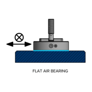
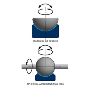
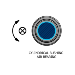
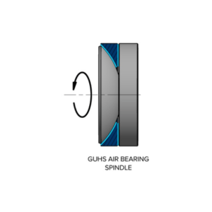
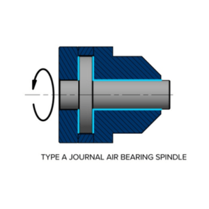
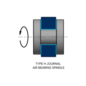
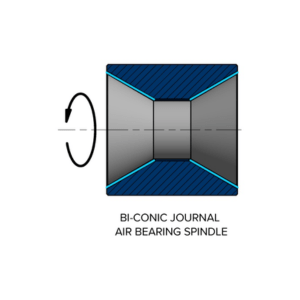
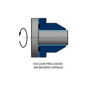
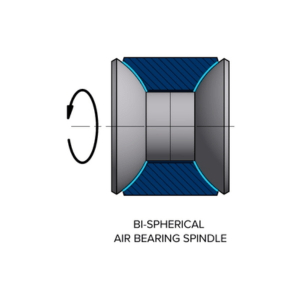
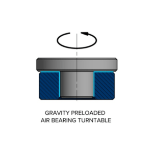
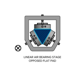
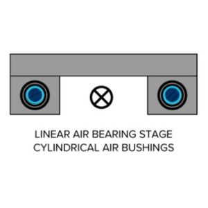
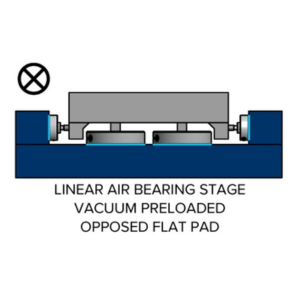
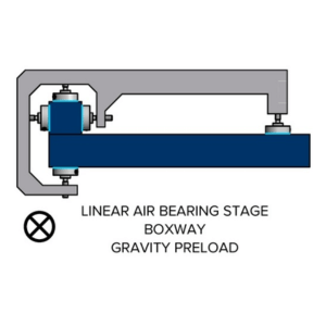
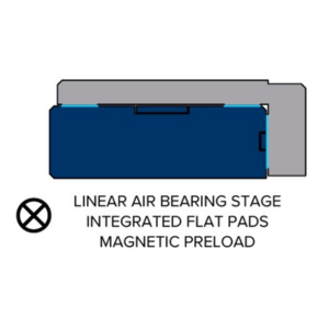
There are several ways to configure air bearings such that movement is restricted. A few configurations are shown below to help in establishing a base level of understanding. Deep blue shading designates fixed elements, whereas grey shading designates moving parts. The contour of the air gaps is bright blue.
SINGLE SURFACE AIR BEARINGS
Flat Thrust Air Bearing
Spherical Air Bearing
Cylindrical Bushing Air Bearing
SINGLE-AXIS ROTATING AIR BEARING SPINDLES
GHUS Air Bearing Spindle
Type-A Journal Air Bearing Spindle
Type-H Journal Air Bearing Spindle
Bi-conic Air Bearing Spindle
Vacuum Preloaded Air Bearing Spindle
Bi-spherical Air Bearing Spindle
Gravity Preloaded Air Bearing Turntable
LINEAR STAGE ASSEMBLIES
Cylindrical Air Bushing – Opposed Flat pads

Opposed Flat Pads on Triangular Rail
Dual Cylindrical Air Bushings
Vacuum Preloaded Flat Pads – Opposed Flat Pads
Boxway Flat pads – Gravity Preloaded Pad
Integrated Flat pads – Magnetic Preload
Contact us now for the Best Prices & Ready Stock!

